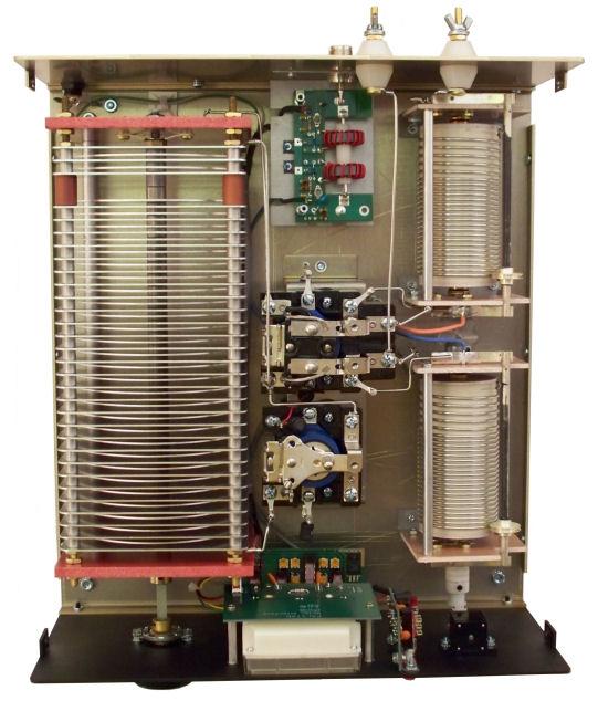
This design allows for easier matching of the 50 ohm load on the input side as well as wide range matching on the load side. Note that the T network is really just 2 L networks fixed back to back with a common inductor. The T network is a 3 component design that is found in the vast majority of 3 element tuners available today. In order to service both hi-Z and low-Z impedance matches, the topology of the network must be changed.Ĭonsiderably more expensive and complicated to implement if switch gear, power and relays are required to cover both high and low Z impedances. Simple to implement for either hi-Z or low-z, but not both Lower power losses due to heating than the standard PI-network illustrated above Inexpensive to construct if the matching requirements for the feed line and load are not particularly wild Will resolve to only one point of resonance for a given frequency and load impedance The L network topology can be changed to be fully symmetric for better support of coax to ladder/window line transmission line. The L network depicted above is not symmetric and thus unbalanced, meaning that it is best utilized in coax to coax antenna tuners. This is true for both the capacitors and the inductor. In some matching conditions the larger variable components may be switched out altogether in favor of much smaller fixed value components. Roller inductor values range from 2uh to 20uh. Typical component values for the variable capacitors range from 20 - 500pf and up to 1000pf for fixed value capacitors. There are many tuners that accomplish this task by using a set of rotary switches configured to move the capacitance from one side of the inductor to the other to further add additional capacitance to the network. Depending on whether the impedance is greater on the output or on the input side, the shunt capacitor must move from one side of the inductor to the other. The topology of this network must be changed to support the direction of match.

Power loss due to heating in this network is higher than that of the L network and significantly more than that of the symmetric PI networkĥ00 pf capacitors can be large and expensive If tuned to an incorrect resonance point, power loss due to heating of the roller inductor will result More than one resonance point can be found using different component values More knobs means more time required to find a good match

Basically it's not symmetricalĪnd thus better suited for coax to coax antenna tuners.īroad banded, able to match a wide range of impedancesĬan be modified to allow for the selection of lower value variable components by adding additional fixed components to the input side of the network

The circuit depicted above is unbalanced in that the "hot" side is treated differently than the "shield" side of the tuner. The difference between the settings results in higher or lower efficiency and thus power lost to heating.Ĭomponent values generally range from 10-500 pf for the variable caps and 2-20uh for the roller inductor or tapped coil. A concern for the Amateur Radio Operator is that the PI network, just like the T network, can produce resonance at more Generally the design calls for fairly large variable capacitor values and as such can be expensive to build. The PI network is considered to be a low-pass filter and normally contains 3 tunable components. The Pi-Network circuit, as depicted above, is found in both antenna tuners and as tank circuits in older tube style transmitters and linear amplifiers.


 0 kommentar(er)
